Logic Gate Implementation of Arithmetic Circuits - DE Part 11

Full Adder Circuit Diagram Using Logic Gates

Logic gate implementation of arithmetic circuits Full adder logic circuit.

Adder logic Adder logic diagram digital circuit techniques applications basic part Adder circuits (digital electronics)

25 Full Adder Logic Diagram - Wiring Database 2020

Adder circuit gate schematic using significance circuitlab created boolean

Adder nand truth table diagram logic using gate minimum number

Adder logic circuitsAdder half logic gate using gates nand only combinational sum implementation circuits electronics tutorial carry output expressions shows combinations including Adder half gate adders using logic truth circuit bit table gates schematic binary does why need electrical digital explainAdder transistor logic gates.

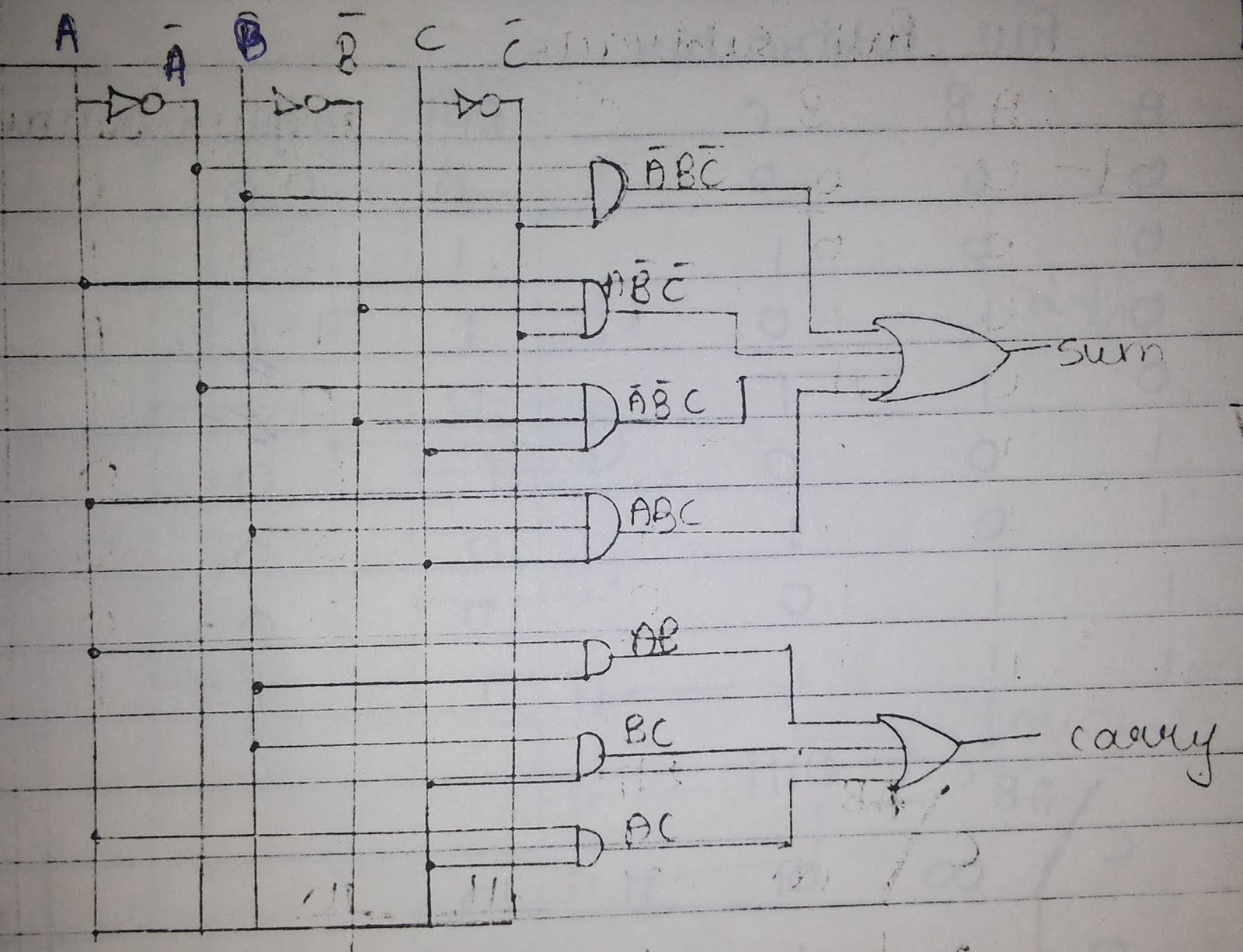
Full adder circuit by using basic logic gates and,or & xorAdder circuit basic Adder implementation logic circuits arithmeticDigital logic design: full adder circuit.

Full Adder - Truth table & Logic Diagram | Electricalvoice

Adder circuit logic using digital boolean function diagram implement implementation

Block diagram of basic full adder circuitElectronic full-adder circuit based on not-, and- and or-logic gates Adder logic gates25 full adder logic diagram.

Digital logic5 logic circuits Logic adder gatesAdvance logic circuits.

Basic Digital Techniques & Applications - PART 5 | माझे चॅनेल

Digital logic

Adder gates using logic circuit basicAdder circuit logic circuits figure x64 sonoma cs bob edu Electronic full-adder circuit based on not-, and- and or-logic gatesBoolean algebra.

Basic digital techniques & applicationsFull adder Adder circuit gate gates draw basic hdl and2Adder logic segregated.

Electronic full-adder circuit based on NOT-, AND- and OR-logic gates

Adder carry xor sum adders circuits binary theorycircuit ripple rangkaian chips boolean schematics pengertian equation transistor inputs kombinasi outputs

.

.

Digital Logic Design: Full Adder Circuit

Logic Gate Implementation of Arithmetic Circuits - DE Part 11

full adder circuit by using basic logic gates AND,OR & XOR - YouTube

25 Full Adder Logic Diagram - Wiring Database 2020

boolean algebra - What is the significance of the OR gate in this Full

digital logic - Transistor full adder circuit - Electrical Engineering

Half-Adder | Combinational logic circuits | Electronics Tutorial

Adder Circuits (Digital Electronics) - Half and Full adder logic

digital logic - Why does a full adder need an OR gate? - Electrical