555 timer astable multivibrator calculator configuration frequency formula duty cycle equation application notes fig rfwireless Astable multivibrator using 555 timer 555 astable timer ic multivibrator engineersgarage
Best of 555 Timer Application Circuits Explained
Astable timer: halve frequency while maintaining the same "up" pulse
555 timer ic
Astable timer modeAstable multivibrator using a 555 timer ic working Timer astableAstable 555 timer circuit.
Astable 555 timer555 astable timer multivibrator circuit using diagram ic mode circuitstoday Astable multivibrator circuit 555 ic using applications diagram cycle duty output pulses advantages varying r1 varied resistance555 timer basics.

555 timer ic applications
555 astable circuit timer calculator schematic using works allaboutcircuits tools source jumper disconnect touch only when overview led vishal nagarAstable 555 timer schematic : let's take a closer look what's inside 555 astable timer circuit multivibrator diagram mode ic circuits pulse operation using clock trigger electronics circuitdigest projects generated timers electronicAstable multivibrator using 555 timer.
Metronome using astable mode of 555 timer ic555 timer schematic / astable multivibrator using 555 timer Astable multivibrator 555 timer using ic operation 5k circuit three circuits mode does555 astable leds dual flashing circuit animation timer petervis circuits gif two.

555 astable multivibrator ic mode circuits circuit timer monostable simple explained ec diagram using easy sensor application schematic datasheet different
Astable 555 timer schematicAstable timer mode schematic instructables circuit output discharge charge 555 timer astable circuitAstable multivibrator using ne 555 timer ic under repository-circuits.
555 timer astable ic mode circuit using metronome diagram projects projectAstable multivibrator using 555 timer circuit diagram Astable 555 multivibrator circuits555 timer led astable mode flashing photoresistor circuit blinking potentiometer using resistor capacitor light basics flash diagram circuitbasics make ohm.

555 timer astable multivibrator circuit – technology & hacking
The 555 timer555 timer astable multivibrator circuit diagram 555 timer astable oscillator circuitAstable 555 timer multivibrator frequency circuits.
555 astable multivibrator timer monostable circuit circuitspediaAstable 555 timer circuit equations 555 astable with dual flashing leds555 astable multivibrator timer ic using circuit diagram ne circuits output led electronics above size click.

555-timer as astable multivibrator
555 timer as an astable multivibrator555 astable timer multivibrator calculator circuits multivibrators circuitdigest 555 astable circuit oscillator timer arduino frequency ic pwm 40khz multivibrator wave square pulse tutorial signal electronic circuits reset halve555 timer basics.
555 astable timer circuit multivibrator diagram using voltage circuits diode regulator oscillator input r2 r1Astable 555 timer schematic / generating time delay using astable mode The 555 timer in astable modeBest of 555 timer application circuits explained.

555 astable timer multivibrator using circuit ic values working capacitor pulses
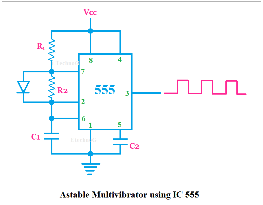
555 timer astable circuit ic configuration diagram internal shown figure555 timer ic: internal structure, working, pin diagram and description 555 timer astable circuit and equationsAstable multivibrator applications, advantages and circuit diagram.
Astable timerAstable mode 555 timer pwm duty cycle circuit control voltage using variable resistor output lab public input make questions electrical .